 with Larry Harris
Adjusting Valve Lash On The 8 Valve Engine
This is the first of a series from the factory service manual on how to take care of your Samurai. This information is adapted from the 87 version but it does apply to all 8 valve engines.
 So what is under your hood? For many we do not worry about what is there until it starts making an unusual noise or strands us on the trail. Don’t let this happen to you, be prepared and perform a bit of maintenance. As some of our trucks near their twentieth birthday a weekend spent with a wrench in hand will go a long way to ensuing a great trail ride.
The stock Suzuki engine is a water cooled in line 4 cylinder, 4 stroke cycle gasoline unit with a single overhead camshaft valve mechanism arranged for a “V” type valve configuration. The camshaft is mounted over the cylinder head; it is driven from the crankshaft through the timing belt, no pushrods or hydraulics are provided in the valve train system.
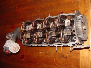 The cylinder head is made of cast aluminum alloy had has four combustion chambers arranged in line. Each combustion chamber has an intake and exhaust port. The camshaft has eight cams, and each cam operates the intake or exhaust valve through a rocker arm. The valve lash can be adjusted by turning the adjusting screw on the rocker arm after loosing the lock nut.
So what does all this mean? It is mechanical, it is old and If you do not take care of it breakage will happen at an inopportune time. The good news is inspecting and adjusting the valve train is easy.
 1 – Exhaust valve.
2 – Intake valve.
3 – Rocker arms.
4 – Camshaft
Why adjust lash? To little clearance between the rocker arm adjuster and the valve the valve would never close Especially true when the engine warms up. This would cause a terrible loss of horsepower and a poor running engine. It will in the long run cause mechanical failure in burnt valves. To much lash (clearance) and we will have noisy operation and low horsepower, the valves will not open enough to allow the proper air and fuel charge into the cylinder.
The factory manual tells us to loosen the adjusting screw locknut make an adjustment by turning the adjusting screw. After adjustment tighten the nut to specified torque while holding the adjusting screw stationary with a straight headed screwdriver, and make sure to recheck the that the gap is within specification. Sounds easy?
What Is Lash And How Is It Adjusted?
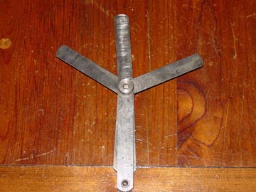
 Valve Lash or clearance is nothing more then the gap between the rocker arm adjusting screw and the valve stem. A thickness gauge is used to measure this gap at “A”

The Nuts And Bolts Of The “How To”
Stop by your favorite online Suzuki Parts supplier and get the required parts for the job at hand. You will also need a basic hand tool kit.
This is a real good time to change the distributor cap and rotor.
-
Valve cover gasket kit.
Make sure to get the kit that comes with the seals that are on top of the valve cover.
Remove the cylinder head cover. It may be necessary to loosen the distributor to clear the vacuum advance when lifting the cover off the engine.
There are four bolts on the top that thread through the cover in to the head. Do not pry on the valve cover to remove it. A tap of a rubber mallet will break the seal.

Standing on the drivers side look at where the engine and transmission come together, remove the ignition timing check window cover from the clutch housing of the transmission. It is that little dirty rubber plug.

Turn the crankshaft clockwise when viewing from the front of the truck. Align the “T” on the flywheel with the notch on the transmission case. This puts the number one piston at Top Dead Center (TDC). You may have to clean the flywheel off at the timing marks. Once clean use a bit of chock to highlight the markings. This will come in handy when you set your timing.

Remove the distributor cap and check that the rotor is positioned as shown. It is pointing to the number one plug wire, If the rotor is out of place turn the crankshaft clockwise one full turn, 360 degrees. With the engine aligned in this position check and adjust valve lash at valves 1, 2, 5, and 7. Rotate the crankshaft one turn, and check the valves number 3, 4, 6 and 8. I find it helpful to mark the valves with a dab of grease as they are adjusted. If you look at the rocker arm and cam you will see the arm is riding on the “Heel” or low section of the cam.

The valves are numbered from the front to back starting on the passenger side. Intake valves are on your left and exhaust are on the right when looking from the front of the engine to the rear.
So number 1 is the first intake valve on the passenger side closest to the front of the truck. The number 5 is the first exhaust valve on the drivers side closest to the front of the truck.

The Most Important Section
It can take many years to learn the feel and use of a thickness gauge. It is a judgment call on how tight or loose the object measured really is. I have a better way to use this tool, it takes all the “feel” out of the equation.
We are going to use the “go” – “no go” test. With this method anyone can adjust valves.
Here is how it works. On a cold engine our adjustment range on the intake valve is 0.13mm – 0.17mm, select a number in the middle of this range. In this example we will go with 15mm. Now for the “go” – “no go”. On the thickness gauge pick one number higher and one number lower on the then the desired value of 15mm. In our case this will be 14mm and 16mm. Isn’t it great we do all the math for you 😉
 How To Adjust
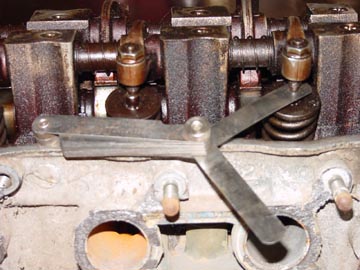
Using a 12 mm wrench on the lock nut and a flat blade screwdriver loosen the locknut on the number one intake valve. Loosen the adjusting screw, Place the 14mm thickness gauge between the valve and the adjusting screw, lightly tighten the adjustment screw until it just touches the valve (thickness gauge). Now holding the adjusting screw so it does not turn tighten the locknut.
Pull out the 14mm gauge and try to insert the 14mm and the 16mm gauge. The 14mm should “go” and the “16” should “no go”. At this point you can use the 15mm selected as our desired measurement and see how it fits or “Feels” it should have a slight drag as it is moved in and out between the valve and the rocker arm adjusting screw.
Mark the valve as complete with a dab of grease and move on to the other valves in the first turn.
Complete this sequence on all valves. Rotate the crank as in the instructions above and complete the remaining valves.

Install a new valve cover gasket and bolt seals, install valve cover, do not over tighten the valve cover bolts! Set the timing, lock down the distributor bolt, close the hood and take a test drive 😉 
08/11/10 14:39:31
