
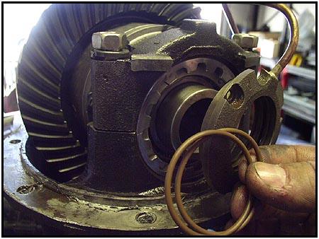
 The o-rings are the most critical part of the air seal. When installed, they create an air chamber that ‘floats’ on the bearing journal. The air comes in through the seal housing and is plumbed through the journal wall into the interior of the carrier. Give the o-rings a good coating of oil before installing them in the seal housing.
 Also make sure the o-rings aren’t twisted in the grooves. Click on the photo to the right (you can do this with any of the photos) to get a good look at how the two o-rings border an air channel that we talked about earlier.
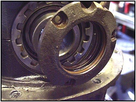
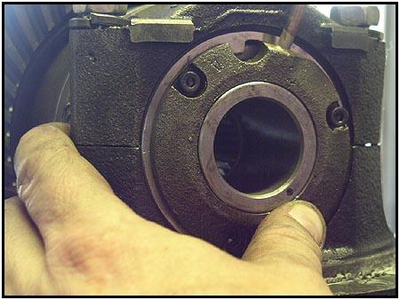 Sliding the seal housing onto the bearing journal, you should use a gentle twisting motion. Don’t pinch the o-rings as they slide over the end. Pay special attention to the notch just left of the air tube. This is where the bearing adjuster stopper has to line up with an open notch on the adjuster ring. See the center picture below to see it in place. Using a small screwdriver we aligned the bolt holes in the seal with the tapped holes in the clamping plate we installed at the top of this page. We added the three cap screws using locktite to make sure things don’t come loose later on, but at this point we left them finger tight.
Now here is a step often neglected but very important. This is where you bench test the system and center the seal housing all at the same time. Applying air (90 psi) to the system, and then rotating the carrier will center the seal housing. At this point we slowly tightened the cap screws to 3.5 ft.lbs. If you over tighten the cap screws you will deform the clamping plate and that could cause premature failure of the seal when the cap screws fall out.
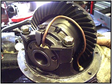
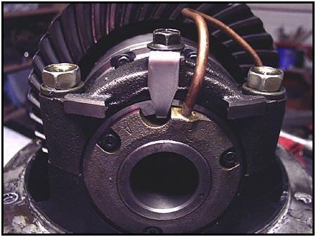

This is what it should look like when it is finished. Notice how the air tube has sweeping bends and stays away from the gear teeth. The locking tab has been put in place and the unit is ready to go into the sidewinder axle we installed in the last issue.

 Next issue we will show you how to convert an existing (Samurai) ARB 26 spline rear carrier to fit the 22 spline front axle in a Samurai. That way you can just move the ARB you spent money on last season to the front and end up with two air lockers.
But as long as we are talking about the Track/Kick differential, let’s take a look at an option many folks are considering to make their axle ‘that much more bulletproof’. The rear axle on a Samurai uses a 26 spline shaft. Although we are using a set of chromoly shafts from Spidertrax, they also offer a larger set of 27 spline axle shafts for more strength.

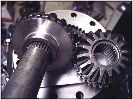
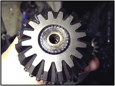 On the left you can see the 26 spline axle in a normal ARB side gear from this months installation. On the right you can see how much larger the opening is in the 27 spline side gear when we put the same shaft into it. These side gears are a direct replacement and can be ordered separately from your ARB distributor or already installed in a new ARB air locker prepared by the shop you get your 27 spline shafts from.
Check out part three of this series and see how easy it is to do a side gear conversion in an ARB Air Locker.
Pt3-ARB ‘Rear to Front’ Conversion
Source:
ARB Corporation LimitedAir Locker Inc. 20 South Spokane Street Seattle, WA 98134 Tel: 1-206-264-1669 Email: sales@ARBUSA.com
08/11/2010