
Grouche Gets a New Lift
Finally to the meat of the article, the installation. I used the instructions from the Rocky Road Outfitters that came with the kit components I had ordered. Like a kid in a candy store is the best way to describe me when all the pieces arrived at my door. I opened all the boxes and made sure everything was there. I had ordered the Rear to Front spring kit, shocks, and the Spring Perches.
I knew I was to write about my experiences with the install, I also knew it can be PITA to install and take pictures at the same time, I needed help. A call to my good friend Jim Mazzola and plans are made. Working on a Zook is fun, working with friends is great fun!
I packed everything up and head off to Jim’s. We have the kit components and the axle housings I received from Rod’s Used Samurai Parts in tow.
Rocky Road Outfitters instructions:
Note: Some Steps modified to fit my installation:
 The SPOA kit can be installed by anyone with medium level mechanical skills. You should plan on having the vehicle down for a day and perhaps two depending on how meticulous you wish to be. Installation really is straightforward and hopefully our instructions will make the job flow more smoothly. Use your common sense as much as these instructions for a successful installation. Items you’ll probably want to have on hand to complete the installation: A metric wrench set, hand sledge, pickle fork, needle nose pliers, grinder, vice-grips, floor jacks and stands, and a camera to document the installation of your cool new Lift Kit. And don’t forget the welder! You will have to weld the spring pads, and shock mounts on this kit.
Step1: Make sure your kit is complete. For each kit, you should have lower front, upper rear, and lower rear shock mounts, 3 brake lines (88 and earlier have a 2nd rear brake line sold separately), 4 spring pads, 2 driveling spacers with bolts, and a Zlink steering arm.
Note: I did not order the brake lines, drive shaft spacers or Zlink steering arm.
Step 2:
 Park your vehicle on a flat level surface for installation. You’re going to be crawling under this thing for at least a day and you do NOT want it shifting and falling. It is best to straighten out your steering so the front tires face directly forward as well. Your steering wheel should be centered. Keep the steering wheel in this position throughout the installation procedures.
Step 3: Loosen your lug nuts in preparation for tire removal. Elevate your Samurai and support it with jack stands such that the wheels are off the ground. Remove wheels, front and rear drive shafts, and shocks.
Step 4: Remove the existing drag link. This is the smaller steering link that connects the steering box and the tie rod. You must remove the retaining clips first with a pair of needle nose pliers. Discard these clips as you will not reuse them in the installation of your selected steering system. After removing the clips, undo the two castle nuts and set them aside for later use. Now you are ready to pull off the stock drag link. Most times a whack or two with a hand sledge on the eye-holes will be enough to release the drag link. Sometimes, a pickle fork might become necessary. The pickle fork is carefully inserted between the steering parts and tapped with a hammer until the two parts release and separate.
Note: I use a small two leg gear puller to remove mine.
Step 5: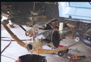 Remove brake lines. We find it easiest to minimize fluid draining by crimping the rubber brake lines tightly with some vice-grips before removing the lower line from the axle. You will be replacing the brake lines altogether later on. You will have two front lines and one rear (pre-88 uses 2 rear lines). You must also remove the parking brake cables from each rear drum. Pull the cable aside for later reinstallation.
Note: This is a good time to change your brake fluid. I say drain it into a safe container for later disposal.
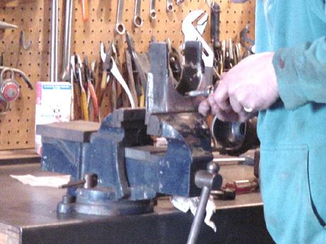
Step 6: Remove the axles. First remove the “U” bolts and spring plates, discard old U bolts. . We also take the time to cut off the old shock studs from the spring plates. It just looks like a cleaner install. Support axle with a floor jack before undoing the shackles. Then, undo the shackles from the frame and lower the axle housing. The axle assemblies can now be pulled aside for SPOA modification.
Note: I used the new spring plates and bolts from Breeze and Spidertrax. I did not modify my stock plates. Rocky Road has new “U” bolts that can be ordered when you buy the kit.
Step 7: For the front axle, you may need to grind off the “U” bolts locating pads on top of the axles with the 5.5″ spring pads. Basically, you want the spring pad to sit nice and firm in the existing spring pad. It should also sit parallel to the stock spring pad. Slight nicks won’t hurt the housing, but be still be careful while doing the grinding.
Note: I did not remove the U bolt plates.
Step 8: Flip the centering pins on the springs. You will notice some pins in the middle of your springs. You must remove these and turn them over so the round bolt head now sits under the springs. Use a “C” clamp to hold the spring pack together. Install a new center pin.
Note: Not included in the kit.
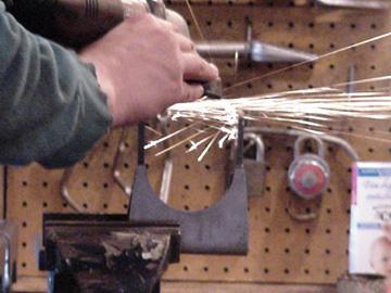
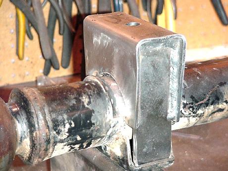
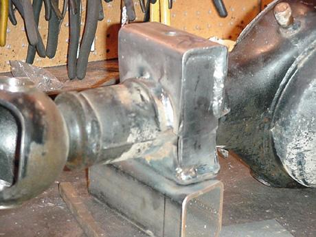
Step 9: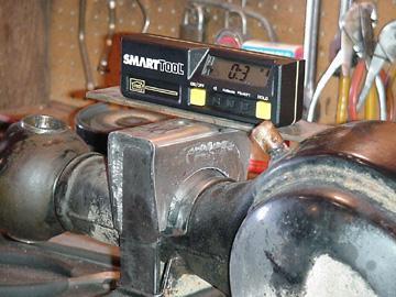 Time to weld. For proper castor setting, the front spring mounts MUST be welded exactly parallel to the lower spring mount. The spring perches should self align, but certainly verify this for your vehicle. If the spring pads do need to be adjusted, you can fine tune by grinding the arms. After positioning, weld a small bead on the top of the axle, and on the two sides of the axle, on each side of the spring pad. Now completely weld the arms of the spring pads to the stock lower spring pad.
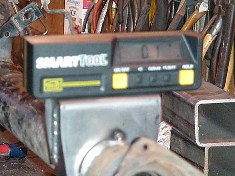
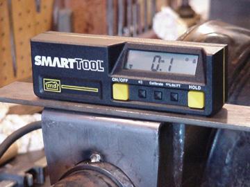
Note: The passenger side perch took a great deal of tuning in order to achieve the fit I desired. The gap between the perch and the axle was a bit large for my comfort level. You should know I am a perfectionist to the point of being anal! When Jim and I got ready to weld the perch on we made sure it was within degree of stock in both directions. The perch on the passenger front axle will require some “tuning” to get the best fit. Jim and I spent some time to get it past our very stringent requirements. You know it is tough when you see a height gauge and a digital angle finder.


Out of the box

Adjust to fit
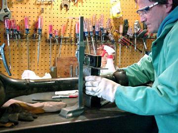
Measured both side for proper height.

Weld the gusset

Small beads, lots of cooling time between
Step 10: The front shock mounts are marked driver’s side and passenger’s side. There is also an arrow which points forward. The surface upon which these directions are written is the surface that will be in contact with the stock spring pads. The contour of the mount helps you easily align the mount to the spring pad. Clamp it in place for some tack welds, and then complete the welding process. Basically, your front lower shock mounts should point back to the rear, with the shock studs on the ground side. The completely flat side of the shock mounts will be facing upward. For fine tuning, we recommend actually mounting the top of the shock to the upper shock mount and letting it hang down. Then simply place the lower shock mount in place so that it lines up properly.
Note: I really like this mounting system!
Drivers front out of the box with a good fit.


Passengers side welded

Step 11: Weld the rear spring pads on now. Same story as the front, but you can tilt the pinion up to 3*. To do t ‘his you will have to grind on the arms of the spring pads again. You will have to slip the arms of the spring perches in between the axle and the brake lines. Just give them a bit of clearance and be careful not to hit the brake line with your welder, it will burn through.
Note: The fit here was perfect! Dropped them on, measured and welded. When you weld on the new perches make sure you allow time for the welds to cool. Run them in short beads. We did mine in 8 steps. Front then rear on the gussets, right side front, left side rear. Each time only running a 1 inch one or less bead, each time allowing them to cool. You do not have to have a heavy bead. Look at stock weld and try to duplicate it.

Perfect fit out of the box

Step 12: After painting the rear upper shock mount (if you want), install by slipping over the stock upper shock studs and reusing the nuts and washers. Keep in mind that we’ve seen these factory shock studs out of whack as much as 3/8″ from one vehicle to the next. We do ‘egg’ out the holes a bit on our upper rear shock mount to accommodate for some fitment. If yours is one of the more out-of-whack ones though, you may have to egg the holes out a bit more on the upper rear shock mount to get it to fit. Or do a slight bit of grinding on the stock shock studs so ours will fit.
Note: Took a bit of work here to get it installed. Mine was one of the really out of alignment. I ended up making lager holes in the bar.
Step 13: Time for the reinstall of your axles. But first, we recommend painting your spring pads at this time. Remove all the residue from welding with a wire brush and paint the spring pads and axles around the welds Put them in place and lift with a floor jack. Install “U” bolts and spring plates to attach the axle to your springs.


Step I4:
With the axles now in position, now is a good time to swap the brake lines. Since you already have the lower ends of the stock lines disconnected, begin by attaching the lower ends of the new brake lines to the axles. Be careful of dripping brake fluid as it can make your paint bubble if left in contact. Also note that the rear brake lines will have to be “worked” into place. Reinstall the parking brake cables.
Step 15: Install lower rear shock mounts. You’ll just have to look at things carefully to make sure everything lines up well. Best placement of the mount points them to the rear of the vehicle and pushes them as far outboard as is possible with a slight upward rotation. You want them so that they are almost touching the “U” bolts. Also place them so that they are on the bottom of the axle. The “L” shaped bracket should go under the axle for best long shock fitment. Tack in place, check position with a shock, complete the weld.
Step 16: Reinstall your drive shafts using your new drive shaft spacers. The spacers go on the axle end of your drive shafts. Install you new shocks front and rear. Larger shocks can sometimes cause clearance problems. Scope out clearance on your brake lines and exhaust to make sure everything will fit. The exhaust may have to be modified slightly to work with some shocks in the new placement.
Note: I used the spacer in the rear only. I have a custom drive shaft in the front.
Step 17: Give it a good ‘pre-flight” to make sure everything is on and works. After a few hundred miles park the truck and recheck all your work. Make sure all the bolts are tight!
08/11/10 15:22