 with Larry Harris Model Kayla King
Petroworks GRSII Install
After discovering some real trails at the first ZookiMelt I found I wanted more crawlability! One quick call to Rudy at Petroworks and my GRSII was on the way. Waiting for the UPS person was terrible, I even asked my wife to be sure to call me at work when the kit arrived. About a week later I get the highly anticipated call from home, its here! So much for working the rest of the day. Call the boss, “hey my Suzuki go slow parts are here and I am going home”. He even understood. The t – case is out of the truck in no time and on the bench. Dang, in a hurry forgot to drain the oil. Big mess as I split the case. So I clean work surface and decide to read the instructions. Off to the library. Great instructions, very clear with good pictures for the guys. As you know pictures for the men, written instructions for the women 😉
This kit can be installed by anyone with average mechanical ability, a factory service manual and patience. Read the instructions, did I say patience? It will not take long and you will be much happier if you take your time on this project. There are a lot of parts in there. You need to understand the names, what they do, how the case comes apart and how it goes back together. A Suzuki T-case is pretty forgiving, but why push your luck. Follow the instructions, take your time to get the clearances correct and your case will live a long happy life. The “Gear Reduction System” kit is easy to install with only a few special tools such as snap-ring pliers and gear pullers.
Torque Chart
Parts List
Fastening Parts lb – ft Front case bolt Center case bolt Counter shaft lock plate bolt Universal joint flange nut Transfer mounting bracket bolt Transfer mounting nut Cross joint bolt and nut Oil filler and drain plug 9.5 – 16.5 9.5 – 16.5 7.0 – 12 80 – 108 13 – 20 18.5 – 25 17 – 21 26.5 – 39 1 – Input gear 1 – Low Output Gear 1 – Cluster Gear 1 – Shaft 2 – Bearings 2 – Washers 1 – Shim Pack 1 – “O” Ring 1 – Center Case Gasket 1 – Front Case Gasket GRS-9006 GRS-9007 GRS-9008 29131-80050 29983-80050 29956-80050 GRS-9009 29975-80050 29525-80050 29535-80050 
1. Remove the transfer case from the Samurai.
Removal Tips:
- Shift the T-case to 4HI (saves digging around in there with a screwdriver later)
- Remove the T-case shift knob, boot and lever (Believe it or not, the lever retainer is much more easily removed from below!) Stuff a rag in the lever hole.
- Undo speedo cable, 4WD switch connector, drive shafts, all lower rubber mounting nuts EXCEPT one for the short arm, just loosen it.
- Remove short arm from the T-case and swing it out of the way.
- Lower the input side of the T-case first, and the case pretty much falls right out.
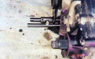
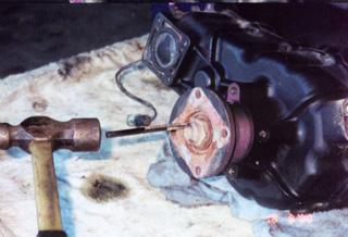 2. Using a pointed punch, uncrimp the large center nuts on the input and rear output flange. Do not uncrimp the nut on the front output flange as its removal isn’t necessary.
Note: I used a 1/4 inch very sharp chisel that had been ground down to fit the notch.
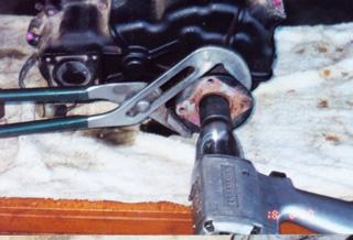 3. Remove the center nuts.
  4. Remove the flanges, using a gear puller if necessary.
 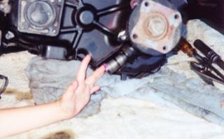 5. With the speedo retaining bolt removed, pull out the speedo gear cup with the speedo gear. This is very important as the cases will not separate with the speedo gear in place.
Tip: This can be the toughest part of the entire process. I used a large pair of channel locks to remove it.
 6. Unscrew the 4WD switch from the front case and remove the ball under it.
 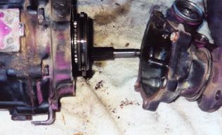 7. Unbolt the front case, leaving the front output flange attached. Slide the front case off the shifting rods.
Tip: Put the bolts in to separate bags and label them, there are several different lengths and they all must go back into the original position.
 8. Using a large screw driver, shift the transfer case into 4WD-HI range to ease disassembly. Note the alignment of the notches in the shifting rods indicating the 4WD-HI range.
Tip: I found it easier to set the T-case in 4WD-HI before removing the shifting lever.
 9. Remove the bolts holding the center case and rear case together. By tapping on the rear case tabs and the output shaft with a plastic hammer or wooden dowel, separate the center and rear cases.
Tip: Put the bolts into separate bags and label them, there are several different lengths and they all must go back into the original position.
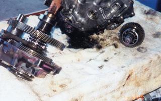 10. Tap out the input shaft assembly from the center case.
 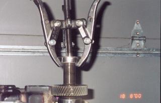 11. Pull the bearings off the old input shaft.
  12. Press the bearings onto the new G.R.S. input shaft. Note how a flange can be conveniently used to stand the shaft on end. Set the new input shaft assembly aside until later.
  13. Remove the countershaft locking tab and tap the counter shaft out of the center case.
  14. … releasing the counter gear, its caged needle bearings, spacer and thrust washers.
 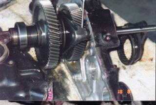 15. With a pin punch, drive the split pins out of the shifter forks. The forks will now slide on the shifting shafts.
 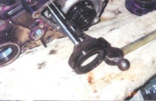 16.Slide the 2wd / 4WD fork off the end of its shaft, letting the 2WD / 4WD shifting collar clear the end of the output shaft assembly and drop off the fork.
 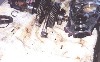 17. Tap the end of the output shaft assembly to ease it out of the center case, while sliding the HI / LO fork off the end of its shaft.
  18. Remove the circlip on the end of the output shaft assembly and pull off the 4wd coupler, taking care not to damage the needle pilot bearing in the end of the shaft.
  19. Remove the larger bearing clip, then pull off the large bearing.
  20. The thrust washer and HI range output gear will now slide off the shaft. Reassembling the output shaft assembly is the reverse of disassembling it, pressing on the pieces you pulled off. Once again, an output flange can be used to stand the shaft assembly on end. Tap the input shaft assembly into the center case. To select the proper end shims for the input and output shaft assemblies, first clean up any burrs in the bearing bores of the rear case and apply a light coat of grease. This lets the rear bearing slide into and out of the rear case more easily.
 21. Put the center and rear case halves together without the gasket and without the counter gear assembly. Squeeze them together so the bearings seat in their bores. Measure the gap between the cases with a feeler gauge. Adjust the gap by adding or subtracting end shims so that it is even, and between .014 and .018 in. when you torque the case bolts, the gasket will compress to.012. This will leave .002 to .0067 clearance. Stick the final shims determined in their bores in the rear case with grease so they do not fall out.
 22. Photo shows both counter gear thrust washers and end shims in place. Stick a counter gear thrust washer in place in the rear case with grease. You should be able to turn the rear case upside down and shake it without anything falling out. Now stick one counter gear thrust washer in place, on its raised shoulder, in the center case using grease. Slide the counter gear thrust washer in sideways, engaging it with the input and output gears setting it on top of the thrust washer. Slide the new counter gear shaft “O” ring end first, through the counter gear and into the case bore until the slot for the locking tab is just sticking out of the case. Rotate the shaft to line up the slot with the hole for the retaining bolt. Install the lock tab and bolt. Slide one of he new cage bearings over the end of the shaft and into the counter gear. Next the spacer and finally , the second needle bearing. Be sure to install the spacer between the cage bearings.
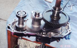 23. This photo shows the center case with the GRS gear set installed, ready to be covered by the rear case. Put the big gasket onto the center case face. Put the rear case over the ends of the shafts and into place, taking care not to knock the counter gear thrust washer out of place. Tap the cases gently together. Put in the bolts holding the cases together. Put the small gasket onto the front case face. Bolt on the front case. Reinstall the 4WD ball and switch. Replace the flanges and nuts.
24. The transfer case is now ready to reinstall in the vehicle. Fill with oil and try.
Fill With Oil Tips:
The transfer case holds 1 qt. of 75 -w-90 oil. To make filling easier they have supplied 2 plastic plugs with the GRS II. When you are ready to reinstall the transfer case in the vehicle try this simple method to fill it:
- Push the small plug into the speedo cable hole.
- Fill the case with about 1qt. of oil ( poor it into the shifter hole)
- Push the large plug into the shifter hole ( these plugs will keep out the dirt and oil in while you position the transfer case onto its mounts and attach the drive shafts.)
- When you are finished, check the oil level with the vehicle level.
- Be sure the fill and drain plugs are secure.
- Remove the plastic plugs, attach the speedo cable and replace the shift lever.
Install Tips:
- Raise output side of the tcase first and position the rubber mounting studs back into the frame.
- Rotate the input side of the case up against the floor.
- Swing the short arm into position and thread the 4 bolts back in.
- Reattach driveshafts, speedo cable, 4WD switch wiring.
- Liberally grease and reinstall shift lever (again, putting the retain in from below is easier), boot and knob.
When first starting off in 4WD LO first gear, don’t touch the accelerator, just engage the clutch slowly, then give it gas as you wish. You’ll have more than enough torque at idle to get the vehicle moving with out stalling.
08/11/10 15:13