 with Tim Tackett owner North Coast Off Road
Installing the Spidertrax Panhard Rod Kit
With 7.5″ of suspension lift, the front axle of Suzi was walking all over the place, making for some interesting steering situations. In some of the crosswinds we have here in Northern Ohio, it could be down right scary. The solution – The long awaited Spidertrax Panhard Rod. The Panhard Rod securely locates the front axle so it can no longer shift from side to side from steering input or rough terrain. The design uses spherical Heim joints to allow for full articulation of your suspension. The kit is pretty straight forward in it’s installation, and all components are typical Spidertrax quality both for good looks and ease of installation. The results? While I still have some minor Caster angle problems to correct from my previous suspension changes, the mushy, shifting feeling in the front is completely gone. Now when you turn the wheel, Suzi responds right now! If you have a SPOA, you really need to try a vehicle with this kit installed, once you drive it, you’ll never be satisfied till you have your own!
Tools/Materials Safety glasses, ear plugs, grinder, wire brush, rust resistant primer or paint, 1/2′ drive ratchet, 3/4″ & 7/8″sockets, torque wrench, 7/8″ & 1 1/16″ combination wrenches, 10 MM combination wrench, pliers, flat pry bar, hammer. It should be noted that the instructions shipped with the kit are slightly different in sequence than this article. The following instructions are an enhancement to the work sequence. Pay attention to the modification of the spring clamp plates not covered in the shipped instructions. Depending on your suspension manufacture and shock mount location, failure to make this modification could permanently damage your shocks. The Install
1) Unpack and layout the components of the kit. Admire the quality and heft of the components, and then check each part against the packing list. If any parts are found to be missing, contact your distributor or Spidertrax.
 2) The Spidertrax instructions direct you to break the driver’s side brakeline fitting at the frame mount. I hate brake fluid, and didn’t want this stuff getting everywhere, nor did I want to bleed brakes when finished, so we will proceed a little differently.
  Take your grinder with a thin (3/32″) cutoff wheel, and cut along the front weld for the brakeline bracket from top to bottom. The brakeline is far enough away that you won’t cut into it.
 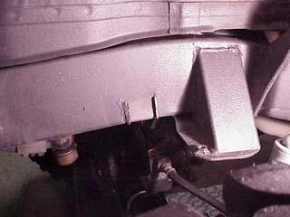 3) Once the front is cut loose, remove the clip holding the line in the bracket, and set it aside. Insert a chisel in the gap, and tap it in with the hammer, spreading the bracket from the frame a little. Grab the bracket near the point the line passes through with the pliers, and start working it back and forth. There is plenty of clearance to do this. After a few cycles, the bracket will break off the frame, and then let it hang on the line for now. We’ll remove it later. Now the bracket is gone, and no brake fluid leaking everywhere!
 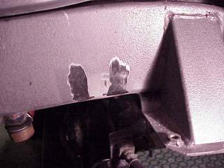 4) Once removed, you will have some metal left on the frame that needs to be ground off flush for the Panhard hanger bracket to install properly. Using the grinder, grind the area flush with the frame. 5) Now place the Panhard hanger bracket on the frame, and mark where the U-bolts will need to pass through the gap between the frame and the inner splash panel. Note the bracket will be setting about 1/8″ from the frame mounted bump stop when complete. You just need the general area marked to know how much of the lip to bend up. 6) Remove the Panhard hanger bracket, and using the pry bar between the frame and the inner splash panel, pry the panel towards the tire so the lip is away from the frame. While holding the lip out, take the hammer and roll the lip upwards so it is flat. Release the pry bar and the splash panel will spring back. Now you need to pry upward between the frame and the lip to expand the gap a little more.
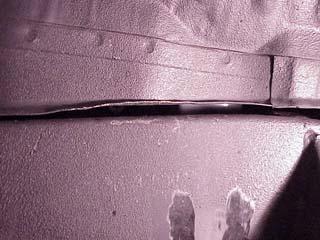

 7) Once you have enough room for the U-bolts, take your primer or paint and touch up any bare areas to prevent corrosion. 8) Insert the U-bolts and the backing plate through the opening. Note the backing plate has a little hole through one side, and this should be down.
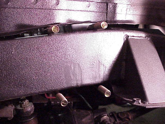
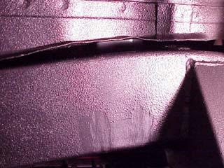
9) Place the Panhard hanger bracket over the U-bolts. Don’t worry if the fender lip is pushing against the bracket, it will move out of the way when the bolts are tightened. Install the flat washers and the locking nuts (called stamped steel nuts in the instructions). Set the bracket 1/16″ to 1/8″ away from the frame mounted bumpstop bracket. Tighten securely with the 3/4″ socket and ratchet. I would suggest torquing to 40-ft lbs. if you have a torque wrench. It helps on this step if you have an air ratchet.

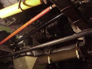
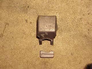
10) Now it is time to mount the spring clamp plates. This is where you may need to modify the Spidertrax clamp plates. If you have lower shock mounts on the bottom of the axle tube outside the springs, you need to do this. The picture shows the orange Breeze clamp plates that we carry for the front springs. You will notice the corner near the shock is radiused away from the shock tube. If you reused your factory clamp plates for your SPOA, you may not have cut the corners off, as most SPOA kits on the market do not address this. If not, I advise for you to inspect your shock tubes for damage. When your suspension flexes, the axle will twist this corner right into the shock damaging it permanently. There is a right and left side bracket and you need to remove the rear corner as shown for each. 
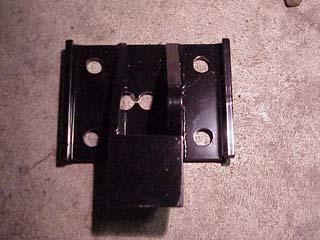
11) Using the grinder and the thin cutoff wheel cut a 45 angle across the corner. You only need about 1/4″ of metal outside the U-bolt hole. Once the corner is removed, radius the 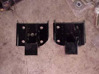 straight cut to a nice rounded shape. Once both are modified, use a high gloss black spray paint to touch up the cut area. If you have a Mercury Marine dealer near you, the Quicksilver brand “Mercury Phantom Black” spray paint they carry for the Mercury outboards is THE BEST spray paint available in the world. It is about $8 to $9 a can, but it is well worth it if you want that glassy look of the powder coating.
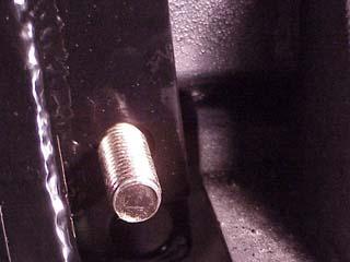
12) Remove the existing clamp plates one at a time, and install the new Spidertrax clamp plates. Note the plate with the vertical mount on it is for the passenger side. Both sides have the bump stop bracket facing out. They also have three holes in them for relocated axles. Use the hole that works with your suspension. Most will use the center hole, just make sure the plate is centered over the spring perch. I suggest the driver’s side first. Install the U-Bolts and washers/nuts you removed, and tighten securely to 45 – 50 ft-lbs. You must torque these bolts; otherwise your front axle may decide to leave when you would prefer it to remain under the truck. Note that once the passenger side bracket is installed, you need to remove excess U-bolt thread above the front two nuts. The Heim joint occupies this area when installed. Cut the excess thread off just above the nut. 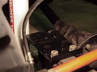
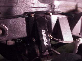
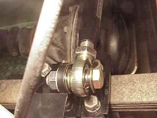
 13) With both clamp plates and the Panhard hanger bracket installed, it is time to assemble the rod itself. Install the jam nuts on each of the Heim joints, and run them all the way down. Thread them into the rod at each end. These are both right hand thread, so you will have to remove and adjust a couple times to get the correct distance. When set properly, you should just be able to insert the 3/4″ bolts snuggly. Once set; lock down the jam nuts on the Heim joints. I waited to do this till after I had the rod installed. There should be the same number of threads showing on each side. 14) Install the rod on the passenger side end, you can lay the other end on top of the lower bumpstop bracket. Note that the misalignment washers mentioned in the instructions, install with the flat sides out, and the tapered end against the center pivot ball of the Heim joint. Install the flat washer and locking nut and tighten securely. Note the nuts are installed on the backside of the bracket; insert the bolt from the front. The pictures below show the easiest placement of your wrenches to tighten the bolts. 15) Move to the driver’s side and install the bolt, one spacer, the Heim joint, the other spacer, then the flat washer and locknut. Note the nuts are installed on the backside of the bracket; insert the bolt from the front. Tighten securely.
 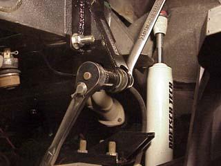 16) Adjust the center rod a turn or two if required to center the amount of thread showing on the Heim joints. Make sure both Heim joints are straight up and down, not leaning to one side or the other. Once satisfied, tighten the jam nuts. Two 1 1/16″ wrenches makes this easier as you can snug in opposite directions without disturbing the vertical alignment of the Heim joint.
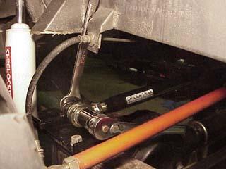
 17) Now the basic installation is complete, it is time for that nasty brake fluid. I used a pair of dykes (wire cutters) to make an indentation across each corner in the thinnest spot of the old frame bracket. You can then take a pair of pliers and while holding the large end, bend this back and forth a few cycles, and the tab will break off freeing the old bracket from the line. Now it is time for a bit of a mess.
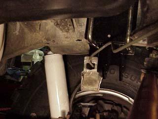
 18) Lay a rag on top of the clamp plate bracket under the brake line joint to catch what runs out. I suggest some rubber gloves if you have them to keep the fluid off your hands. It isn’t good for the skin at all. Take a pair of pliers and hold the flange end of the rubber line, and then with a 10MM wrench, just break the threads to where they come loose. If you work quick, you can minimize this mess, and not have to bleed your brakes. The fluid will start to run out of the hard line once you unthread it from the rubber line. This fluid is coming from the reservoir, and as long as you don’t drain it, you will only need to top it off when finished. The mounting hole is tight, don’t worry about putting the brass mount fully in the hole right now. Quickly unthread the hard line, and insert the brass end of the rubber line through the new mounting hole, threading the hard line back in as quickly as possible. Be prepared to have to wiggle things around a bit to get the threads to line up.
  19) Once you have the lines back together and have wiped up the excess fluid, it is time to fully install the brass end of the rubber line into the mount. The brass end has two flat sides on it. These have to be at the top and bottom for it to insert in the hole fully. The hole is tight, and you will have to wiggle it a bit to get it in. Once in, install the locking clip from the rear. Make sure your brake lines have a half twist in the rubber section to help get the lines away from anything they might hang on. Some people use a weak spring to pull them back out of the way. The lower bump stop bracket is something else for the lines to get snagged on, so pay attention to this area.
 20) Check over all your bolts one more time to make sure that they are tightened securely. Make sure you torqued the axle U-Bolts as well. Impression
When driving the vehicle, you will notice a marked improvement in the steering, it will respond quickly to steering input, and you should be prepared to relearn the handling characteristics.
Editors Note:
North Coast Offroad stocks multiple manufacture’s products for your Suzuki vehicle, including the item profiled above. Visit them at http://www.northcoastoffroad.com
08/11/10 15:22