 with Jim Mazzola
Idler Arm Bracket with BEEF! ATTN: IFS folks.
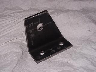
From an engineering standpoint, Ive long been skeptical of the strength of the stock idler  arm on the Tracker when pitted against 31 or larger tires. I inspected it from time to time and found that it just seemed to hold up ok. However, with the arm on the bench my best guess would be that the arm would break right where the blue lines are drawn. Well guess what?, the following picture shows you where it DID break. It did so after I turned the keys over to my 16 year old son and let him drive the grueling 8 hour trail ride in Canada called Gitchee Gumee.
  Its not that my aspiring wanna be Tracker owner son is hard on equipment, its more likely the 100,000 miles or so Ive got on the prototype suspension has finally started to show some signs of fatigue and stress in some of the components that were left in stock form.
So off to the shop to build a better mouse trap. For the backing plate, I more than doubled the thickness to thick. Cut the piece 3 X 4. Lay it on the back side of the old arm and transfer the holes to the new piece of steel and drill the holes out. A little detail on  corners to clean up the appearance. Next cut a piece of 2 X 3- 3/16 wall tube approx. 2 long. Drill a hole diameter in that tube 1 3/16 from the end to fit the original idler arm shaft in. The next piece youll need is the old shaft from the arm. Tap off the shield. Cut, grind, hack that shaft out of the original idler arm bracket. Clean it up so that it fits into the tube cleanly. Here are the parts just before welding. Weld the shaft to the tube first, then weld the tube to the backing plate. Be careful to make sure the shaft is perpendicular to the bolt pattern. Make sure you measure the heights of the bottom bolt holes to the shoulder portion of the shaft. A small difference here wont affect the steering geometry much, however the perpendicularity of the shaft to the backing plate will. After welding the tube to the backing plate theres not much else left to do other that hit it with some paint and bolt it back on. As you can see, its substantially beefier than the stock arm mount
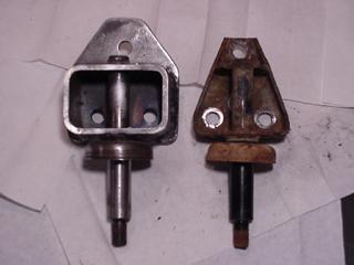
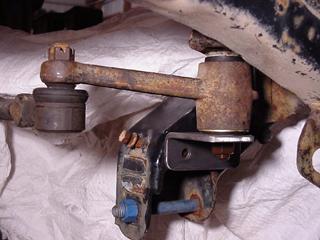
This design is the minimum I would do to reinforce the idler arm to stand up to 31 or so tires. The reason I say this is that this arm is loaded in what is referred to as single shear. Meaning, with enough force on the wheel, the idler arm shaft WILL bend. Theres nothing holding the nut end of the shaft from bending. Mine WAS bent along with being broke when I took it off! Im not a fan of single shear anything. So, to put the arm in double shear, youll need one more piece of steel.
The bracket is a simple 3/16 thick angle that replaces the washer on the idler arm and attaches with two M8 bolts through the lower control arm mount. Cut out the brace as shown and drill the appropriate holes in the frame as shown. This should now make the idler arm pretty bullet proof.
08/11/10 15:25