 with Jim Mazzola – kb8ymf@juno.com
The Elusive Lower Geared Transfer Case
Getting started:
Removal of the transmission / transfer case assembly.
 Follow your basic R&R techniques for removing the transmission and transfer case. These two units come out as one assembly. On the bench youll split the two. First remove the 5 transmission gearshift housing bolts.
 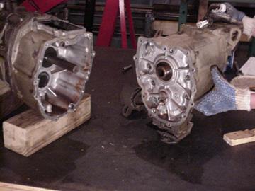 This must be done to access the 1 bolt under the housing. Remove the 12 bolts that hold the two units together. The two halves are doweled together so take your time in splitting them. The manual recommends using a case spreader but with shims and a little care you can separate these pretty easily.
 Remove the transfer case shift lever cover and the big return spring bolt in the side of the gearshift housing. A spring, ball, and hat shaped
  plunger will come out of the hole. Dont loose them! Inside the transfer case is a small cast yoke that the shift lever rides against. Drive the roll pin out of it. The pin will fall down into the case. Dont worry. You have the entire case apart before to long. Just dont forget about it later.
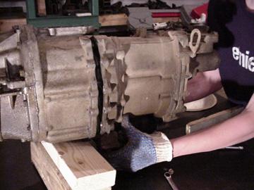
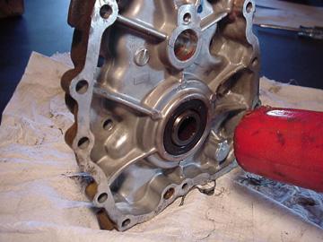
 Next remove the 15 bolts and separate the rear housing from the main case. This joint is sealed with RTV, so separating these will prove to be much harder. Be careful not to loose the shim that may be located on the end of the rear side of the front drive shaft bearing. This will expose the front drive chain. The main reason for removing this side of the case is to clean up the assembly after you grind on the case for an hour or two!
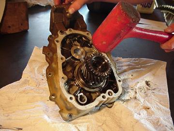
 Turn the case over, well remove the 9 bolts and the one countershaft case plate bolt. This whole assemble can now be lifted off to expose the gears that well be replacing.
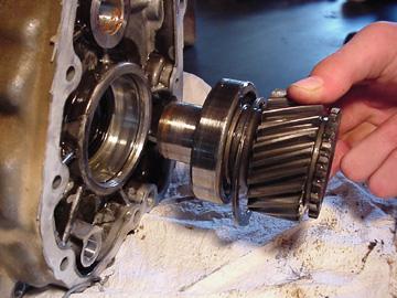
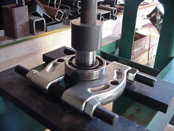
  Remove the front input gear bearing and gear assemble from the front case. This is done by first removing the C clip and tapping it out with a dead blow or non-marring hammer. The bearing needs to be removed from this assembly. Remove the C clip and put the assembly in a press to remove the bearing. You may be able to remove this monkey style (with a pry bar) but I wouldnt recommend it. Dont press the bearing back on yet. Put the parts aside. Assembly of this gear and bearing later on proved to be quite tricky due the increase in gear tooth count.
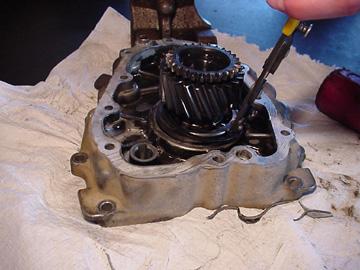
 Well turn our attention back to the main assembly. The countershaft assembly will slide out of the case quite easily. Be VERY careful not to loose the shaft washer balls at both ends of the thrust washer. Use caution when removing the o-ring also. The production manual said to replace the o-ring but I didnt and things seem to be fine. I suppose if your not careful you could damage the o-ring. Do not remove the friction ring that is pressed on the shaft. Remove the shaft and needle bearing and lay aside.
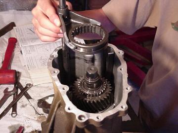 On the top of the case there are two plugs securing the shaft detent balls and springs. Remove these. The shift fork should now be able to be removed from the case. Scribe marks on the clutch sleeve and the center hub to be sure they are reinstalled with the same teeth mating each other and in the correct direction.
Remove the C clip on top of the hub and remove the reduction hub from the rear output shaft assembly. This required a small three legged gear puller. You might be able to work it loose with a die tool but be careful. Remove the output gear and the sleeve bearing from the housing.


08/11/10 15:26