 with Larry Harris
E-Brake Installation
This page is reprinted in part from the instruction that ship with this kit from Spidertrax .
I recently installed the Spidertrax Disk Brake kit and needed a new E brake system. When I ordered my disc kit I went with the E Brake option at the same time. Why reengineer when it has already been done for us? If you have the opportunity, pre fit this kit on your Transfercase while the case is out of the truck. There are three holes on the rear of the TC where the Spot caliper bolts to and these can be a PITA to clean out with the case installed. By doing it the first time out of the truck you will also be able to trial fit all the pieces. Everything fits perfectly! Now is a good time to install those reinforced transfer case arms. I have noted a few places in red text that need special attention. Please see the Review for first impressions.
Included with the kit:
3: Zinc plated steel caliper mounts 2: Aluminum bushing 1: Wilwood mechanical spot caliper 1: Steel rotor 1: 7/32 alan key 1: Steel alignment ring 1: Master link 3: M8x25mm bolts 3: M8x25mm lock washers 2: 3/8×2 flat head screws 2: 3/8 lock washers 2: 3/8 standard nuts 2: 5/16×3 hex bolts 5: 5/16 washers 2: 5/16 nylocks 1: Spring 1: Stainless steel sleeve 1: 5/16×1-3/8 hex bolt 1: 5/16 stamped nut 12: polyurethane bushings 3: 3/8×3 hex bolts 3: 3/8 nylocks 6: 3/8 flat washers Earlier Samurai Models: Small Driveshaft Flange 4: 5/16×1-3/8 hex bolts 4: 5/16 lock washers 4: 5/16 nylocks Later Samurai Models: Large Driveshaft Flange 4: 3/8×1-1/2 button head bolts 4: 3/8 lock washers 4: 3/8 nylocks Figure 6
The E-Brake Kit is an extremely powerful parking brake system for your Suzuki Samurai. It works by attaching a rotor to the output flange of the transfer case. Using a single mechanical spot caliper, the rotor is locked in place preventing the rear driveshaft from turning. By locking the rear drive shaft, the rear wheels will not be able to turn. The Spidertrax E-Brake Kit in four wheel drive will effectively lock all four tires from turning. Tested mine on the hill in the back yard, it holds better then the stocker!!
For hardcore fourwheelers, keep in mind that the rotor in this kit can be vulnerable to damage if not protected. We strongly recommend protecting the underside of the rotor.
You should find the E-Brake Kit to be easy to install. With the exception of drilling two small holes in the side of the frame rail, this kit is completely bolt-on. With that, have fun with your new E-Brake system. If you have any questions or concerns, feel free to contact us. Send your questions to tech@spidertrax.com
PART 1: PREPARATION OF VEHICLE BEFORE INSTALLATION OF KIT
1) Locate a flat level ground for the installation of the E-Brake Kit. Chock both the front and back of the rear wheels and disengage the e-brake.I found it easier to jack up the truck and place it on jack stands. Makes it a lot easier to spin the drive shafts.
2) Remove all existing e-brake cable mounting points at the rear axle. Also remove the guiding rubber grommet found on the floor of the body. The cable can remain attached to the handle.
3) Mark all driveshaft flanges and the two halves of the driveshaft at the slip yoke to ensure that they a reassembled in the same manner. 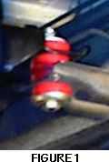
PART 2: TRANSFER CASE MOUNTS
1) Locate the poly-bag in the kit labeled Mounts which contains the 12 rubber bushings. Repeat steps 2 through 7 below for all three transfer case mounts.If you have a reinforced tc mount you may need longer bolts. I was able to use the bolts in the kit, but it was a tight fit. Do not over tighten the new mounts. You need some room for movement here. It is important you do not restrict the movement of the case. I had three threads showing above the nuts when complete.
2) Loosen the upper and lower nuts on the rubber transfer case mount and remove it from the vehicle.
3) Lift the steel transfer case mount slightly and place two polyurethane bushings between the frame member and the steel T-case mount. The steps in the bushings should be opposing each other.
 4) Locate a 3/8-16×3 bolt. Place a 3/8 washer on it, followed by a bushing. Be sure that the step in the bushing is against the washer.
5) From the bottom slide the bolt through the frame member, two bushings and the transfer case mount.
6) Place a forth bushing on the bolt over the transfer case mount followed by a 3/8 washer and 3/8 nylock nut. Be sure the step in the bushing is facing up.
7) Finally tighten the nut and bolt. Be sure not to over tighten. The space between the frame member and the t case mount should be 1 1/16. Figure 1 shows what the proper assembly should look like.
PART 3: MOUNTING THE CABLE TAB
1) For this part, you will need to locate the zinc plated cable tab (the smallest zinc plated part) along with the 2 5/16-18×3 bolts, matching nylocks and flat washers. In addition, you will need a hand drill and a 11/32 drill bit.
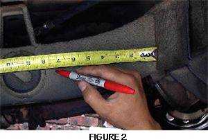
2) Mark the location of the mounting tab on the driver side frame rail as shown in Figure 2. The end of the tape measure should sit up against the forward part of the frame member that accommodates the rear spring. Mark a vertical line at 7 from this point.
3) Mark a horizontal line that is 7/8 below the top of the frame rail. The intersection of this line and the vertical line in will mark the top hole of the cable mounting tab.
4) Mark the second hole location which will be 1 down from the top hole markings made in step 3.
5) Before drilling, align the cable tab with the two marked locations to verify the alignment.
6) Now drill the two marked hole locations with the 11/32 drill bit. It is a good idea to use a center punch prior to drilling. Try to maintain the drill square to the frame rail while drilling. The drill should pass through the entire frame rail.
7) Mount the cable tab to the outside of the frame rail using the two 5/16-18×3 bolts, matching nylocks, and the 4 flat washers. The open end of the tab should be facing up.
8) The e-brake cable consists of two separate sections. The first section extends from the e-brake handle to the driver rear brake drum. The second section is approximately 3 long and extends off of the first section to the passenger rear brake drum. Remove the second section from the e-brake cable assembly. This will leave you with a single cable attached to the e-brake handle.
9) Route the e-brake cable over the frame rail and through the cross member. The cable should then loop around and attach to the cable tab. Secure the e-brake cable by tightening the jam nuts onto the cable tab. Figure 3 shows how this cable should look after it has been routed. 
PART 4: ASSEMBLING THE CALIPER MOUNT
1) Refer to Figure 4 throughout this section to ensure proper orientation of components.
2) Locate the two remaining zinc plated steel parts, two aluminum bushings, two 3/8 flat head screws with matching lock washers and regular nuts, the 7/32 alan key, and one M8x25mm with matching lock washer. Place the M8x25mm bolt and lock washer thru the one steel mount as shown in Figure 4. Fasten the two zinc plated parts using the aluminum bushings and the two 3/8 flat head screws in the configuration shown in Figure 4.
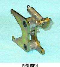 3) Locate the spring, steel sleeve, 5/16×1-3/8 bolt with matching washer and stamp nut. Place the washer on the screw followed by the steel sleeve. Next slide the spring eyelet over the sleeve and secure this to the steel mount with the stamp nut as shown in Figure 4
PART 5: FINAL ASSEMBLY ON THE TRANSFER CASE
1) Be sure that the rear wheels are chocked properly and the vehicle is on flat ground as mentioned in Part 1. To assist in the final assembly, the transfer case should be in 2H and the transmission should be in neutral. Now remove the rear drive shaft completely from the vehicle.
2) Locate the four threaded holes that surround the rear output flange of the transfer case. Three of 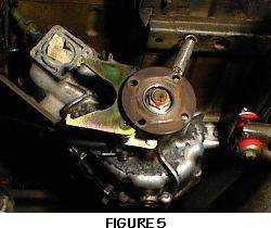 these holes will be used to mount the caliper assembly in part 4. Since these holes have never been used before, spray the holes well with penetrating oil.I used an old bolt to aid the cleaning process. Ran it in like a tap, in a turn out a turn with lots of oil.
3) Using the remaining two M8x25mm bolts and lock washers, bolt the caliper mount assembly (Figure 4) to the transfer case using the holes described in #2. Refer to Figure 5 to ensure proper orientation.
4) Locate the steel ring and press it into the rear output flange of the transfer case making sure that the ring sticks out from the flange at least 1/16.
5) Now is a good time to familiarize yourself with your new mechanical spot caliper. The caliper is a very simple design. Only one adjustment screw is used for calibration. The steel lever arm (arm with 2 holes) actuates the brake pad. Place the steel lever arm so the pad is in the retract position. Back out the adjustment screw to provide enough clearance for the thickness of the rotor. Final calibration will be done in Part 6.
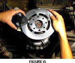 6) Facing the back of the transfer case, hold the rotor in your right hand with the chamfered inner diameter on the rotor facing away from the transfer case. With your left hand, place the caliper over the rotor as shown in Figure 6. The lever of the caliper should be pointing up. Work the caliper and rotor into place. The caliper should fit into the notches of the floating mount and the rotor should fit over the steel ring and lay flush on the output flange. Line up the holes on the rotor with the corresponding holes on the output flange. This rotor is designed to accommodate both earlier and later Samurai models so only 4 of the 8 holes on the rotor will be used.
7) Re-attach the drive shaft so that one end lies flush with the surface of the new rotor. Use the driveshaft mounting hardware found in the poly-bag labeled Driveshaft to fasten the driveshaft and rotor to the output flange. Make sure that the bolt sizes match the corresponding hole sizes that will be used on the rotor. The hardware in the poly-bag labeled ‘Driveshaft’ is designed for the Samurai model you specified when ordering this kit. If the transfer case is of a different year then the one specified, the hardware labeled ‘Driveshaft’ may not work. The head of the bolts fastening the rotor and driveshaft should sit on the flange side of the rotor.
8) Slide the end of the e-brake cable over the steel caliper arm so the e-brake cable hole and the top hole of the steel caliper arm line up. Insert one end of the master link through both these holes, fastening the e-brake cable to the steel caliper arm. The other end of the master link should attach to the eyelet of the spring. Assemble the master link. The master link should now be connecting the e-brake cable, the steel caliper arm, and the spring.It is nice to have the truck high enough to be able to sit up under the body tube and be able to see the spring mounting location.
PART 6: CALIBRATION OF YOUR NEW E-BRAKE SETUP
 Note: This step is critical to the life of your spot caliper pads. It is very easy to do. Please take a minute to go over the instruction again 😉
1) The e-brake handle should be in the down position. Loosen the jam nut in the back of the caliper and finger tighten the adjustment screw until the pads are in complete contact with the rotor. Back the adjustment screw out 1/4 to 1/3 of a turn. Tighten the jam nut to lock this position. At this point the caliper pads should not be exerting clamping force on the rotor and the caliper should have some freedom to move. If the caliper is not free to float, driving the vehicle will cause excess heat to build up in the caliper pads causing them to break down. I can not stress how important these steps are. Please make sure you follow the very well written directions on this step!
2) Take out the slack in the e-brake cable by tightening the adjusting screws at the end of the cable closest to the e-brake handle. The e-brake handle should be in the down position. Do not over tighten the cable as it should NOT exert any force on the caliper and spring while the handle is down.To adjust the E brake, find the cable that is attached to the E brake handle, loosen the 10 mm long nut that is toward the rear of the truck first. This is the lock nut. Once loose turn the adjusting nut to obtain the tension you need.
 3) Pull up on the e-brake handle. The handle should move up approximately 9 clicks. If the handle moves up to much, the e-brake cable tension needs to be tightened. If the handle moves up to little, the e-brake cable tension needs to be loosened. If adjusting the e-brake cable tension does not bring the number of clicks to approximately 9, you may need to double check the caliper adjustment. When making adjustment to the caliper be sure to follow the guidelines in step #1.
4) Now that the e-brake has been adjusted, you should test the e-brake holding force to ensure proper installation. On flat ground, engage the e-brake by pulling on the e-brake handle. While sitting in the vehicle, have someone attempt to push the vehicle from the outside. If the vehicle cannot be moved, continue testing the holding force of the e-brake on inclined hills to further test proper installation. The E-Brake Kit is intended to be used as a parking brake system. Unless in an emergency, do not attempt to apply the e-brake handle when the vehicle is in motion. Doing so could cause serious damage to the transfer case and the caliper. Also, when initially driving the vehicle, you may hear a small noise. This is a result of the caliper pads and rotor coming into slight contact. It is due to the fresh surface of the rotor and should go away within minutes.
5) The caliper is not self-adjusting and will therefore need to be adjusted as the pads wear. If the caliper is set up properly as described above, the pads should last a very long time and only minimal adjustments will be needed.
DISCLAIMERWARNING: FOR OFFROAD USE ONLYINSTALLATION OF ANY COMPONENT OR KIT SHOULD ONLY BE INSTALLED BY PERSONS EXPERIENCED IN THE INSTALLATION AND PROPER OPERATION OF VEHICLE BRAKE SYSTEMS. BEFORE OPERATING THE VEHICLE, TEST THE BRAKES UNDER CONTROLLED CONDITIONS. MAKE SEVERAL PARKING STOPS IN A SAFE AREA ON FLAT GROUND AND ON INCLINED SURFACES.
08/11/10 15:12