 with Rich Davis
Suzuki Samurai 1.3 Liter TBI Throttle Body Injection ECM computer fix
You have been happily driving your Suzuki Samurai now for 10 or so years and it wont start one morning. You pop the hood and tinker around with all the usual stuff, check the spark plugs, wires, igniter coil, fuel pump, relays, fuses, and never realize that it is the computer that has gone bad. The problem is that there are several electrolytic capacitors on the ECM that tend to leak over time and then go bad. When they go bad your engine either stops working or acts very erratically. In the case of your Samurai, it just stops working.
This article will cover replacing those capacitors to fix the most common issue that these ECMs have. If you have never soldered parts on a circuit board before, I dont suggest learning on your ECM; find a friend who knows this stuff to help you. For a basic understanding of how to solder go to this web site.
You will need the following items:
 4 Electrolytic, 50Volt, 105 degrees C capacitors (around $6 from DigiKey, MCM electronics, or such store, NOT at RadioShack)
- 10uF, 22uF, 47uF, 100uF
Figure 1: Normal electrolytic capacitor. This side is the negative terminal of the capacitor
Soldering iron (15-45Watt are typically $7-12 at a RadioShack type store)
De-Soldering Iron (45 Watt Found at RadioShack for around $12)This specific one is Highly Recommended due to its ease of use.
Solder
Fine tipped Tweezers
Wire snips
Knife (Exacto type knife)
Multi-Meter
Grounding Strap (should be able to get from Radio Shack)
Lots of Patience

Once you have your item assembled you are ready to begin.
1. Removing ECM: Disconnect your battery terminals, and then unplug your ECM to get it out of your vehicle. You will likely need a wrench or large screw driver to get the ECM out. Be careful disconnecting the connectors, so they dont get damaged.
2. Before you start: Once you get your computer out and open it up you are ready to begin. Before you do anything, DO NOT TOUCH THE CIRCUIT BOARD until you are wearing your grounding strap. If you dont have one, now would be a good time to get one. If you refuse to get one you can hold something metal that is well grounded, but you are putting your ECM at risk. By doing this you will remove any static electricity charge that may be on you. An example of static electricity is when you scuff your feet across the floor and Shock someone or something. That is an extreme case; however, if you have ANY charge built up on you, it is very deadly to your ECM. It is called ESD (Electrostatic Discharge). I have seen it kill many expensive components and boards and this ECM is an expensive component.
 3. Identifying the Capacitors: Figure 2 is what the ECM looks like when it is opened. Labeled in the picture are the 4 capacitors that need to be replaced. Take a minute to inspect the capacitors and look for signs of leakage. Look for dark gunk stuff at the base of the capacitor or around the leads on this side of the board. Make a note of which ones leaked, the board may need to be repaired at the leak point. On a circuit board the lines are called traces and they connect each component together. When a capacitor leaks, it eats at the traces where it leaked and can eat through a connection.
 4. Capacitor Leads: Take the four screws out that are holding the board in to gain access to the underside of the board. The screws may be a pain to get out, use your best bit or even a small flat head screw driver. Carefully (keeping your hand on something metal to ground yourself or if you are wearing the grounding strap you dont have to worry about holding something metal) look at the underside to locate the pins from the capacitors on the other side of the board. Figure 3 is what you will find on the underside of the board.
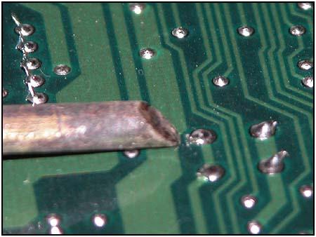
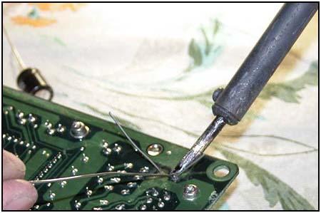
 5. Add solder: Locate the diode posts for your capacitors. Once they are located, use the soldering iron to add some solder to them as seen in Figure 4. By adding new solder to the post it gives it flux which was cleaned off from the factory. This will allow the solder sucker to work in getting the old capacitors out. Note that all of the capacitor legs are bent outwards while all resistor and diode leads are bent inwards.
(NOTE: make sure as you are soldering that any little blobs of solder get carefully picked up with the tweezers, if you ignore them, that little blob may roll under a soldered on component and short two connections together rendering your ECM you are repairing totally dead. This is most important with soldering on the top side of the board.)
 6. Bend the leads straight: Once you have added solder to the leads the leads need to be bent straight. You may need to use an exacto knife to help in bending the leads. I used the soldering iron as seen in Figure 5. Be careful you dont mess up the pad under the solder.
 7. Remove the solder: I use a de-soldering iron as mentioned earlier in this article. There are other methods for removing the solder that holds the capacitors in, but I find that a de-soldering iron works much easier. Hold the iron on the lead until the solder melts then use the sucker bulb to get the solder out, if you hold it on the lead too long, the solder will flow to the other side of the board and will make it harder to get the capacitor out. Part of removing the solder, is to make sure that the suction gets the solder from the top side part of the board, there is usually enough of a gap in the hole where the lead goes through the board, that the suction will get the solder.
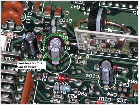 8. Removing the Cap: When the solder is removed use the tweezers to CARFULLY pry the capacitor, if it doesnt easily move, than you may need to use the de-soldering iron again or even add new solder and use the de-soldering iron again to remove the leftover solder. If this doesnt work, hold the soldering iron on the lead heating it while you use the tweezers to pull the capacitor, carefully. Make sure that the tweezers are not applying pressure to other parts on the board (Figure 7). Realize that the capacitors are soldered on BOTH sides of the board. This can make is quite difficult removing the solder and capacitor. A good use of the patience tool.
(Note: Carefully is key, on circuit boards there is usually a pad on both sides of the board, and a connection between the pads through the board, you dont want to break this connection. The pads are what the components are soldered to and are used to connect parts on both sides of the board.)
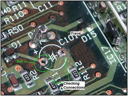 9. Pad inspection: Once the capacitor is removed, inspect the pad for damage, or a break in the connection right around the pad. When capacitors leak, the gunk eats the connection material and can cause the pad to be disconnected from the trace. If this has happened the connection will need to be made again with the use of solder by bridging the gap. This is where you will need to scrape away some of the green stuff near the pad so you can bridge the gap if needed. Use a multi-meter to make sure that the pad shown in Figure 8 is connected to the other side of the board and to other parts that are on the trace. A trace is the wire looking thing on the board that connects different components together
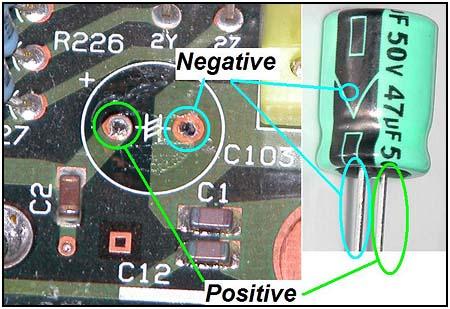 10. Cap orientation: Before you put in the new capacitor, make sure the leads go in the correct position. Figure 9 shows the Polarity positions. On the board the Positive location is marked with a + sign by it. The negative location is not marked on the board, but is marked on the capacitor as seen in Figure 9.
 11. Soldering: Insert the new capacitor. It is VERY important to make sure that you have put it in the correct holes (Polarity, check step 10) and solder the capacitor leads as shown in Figure 10.
 12. Checking the connections: Use the multi-meter to check the connections of the leads with other components that are on the same trace. Make sure you check both sides of the board. Refer to Step 9. Figure 11 is showing the top side of the board where the capacitor is soldered to the top side. The capacitors will need to be soldered to both sides.
 13. Once it is soldered, clip the leads (Figure 12)
 14. Clean up: Make sure you clean the bits and pieces of solder from the surface, again make sure that any bits and pieces on the top side are carefully removed from the surface (figure 13). If they are just blown off, there is a high probability that those pieces will get stuck under a component and short it out. This will kill the ECM.
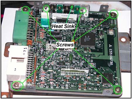 15. Put it back in your rig: Once you have cleaned and checked the connections, carefully put the board back in the case. Make sure you have put in the screws that hold the heat sink (Figure 14). Put the case back together, hook the ECM back into the Samurai, hook up the battery, and pray it will work. This fix is not a Cure-all but is a fix for the most common failure that is found on a 1.3 TBI Samurai ECM.
Note: again if you chose to NOT use a grounding strap, there is a good chance that your ECM is damaged from ESD as talked about in the beginning of the article.

 16. One Satisfied Zooker: Chester was ecstatic when his samurai roared to life after several years of not running. Many of you saw him at the 2005 Zookimelt. When his ECM would die, he would get another one and run it for a little bit till it would die. Now it is fixed and he is one happy driver as seen in the pictures below.
08/11/10 15:18:06