 with Larry Harris
Spidertrax Disc Brake Installation
Proportioning Valve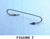 1) A proportioning valve is a must for this brake system to function properly. Refer to the section that corresponds to your vehicle. For all vehicles we are using a Stainless Steel Brakes (SSB) proportioning valve available though most automotive retailers.
?88.5-?95 Proportioning Setup 2) Figure 7 shows the brake line needed to install the proportioning valve. This brake line will have a metric fitting on one end for the master cylinder and a standard fitting for 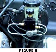 the proportioning valve. The proportioning valve will sit just above and to the front of the master cylinder (Figure 8).
3) First, you will need to disconnect the brake line from the master cylinder that feeds the rear brakes. This is the line closest to the firewall.
4) Cut the flare off the end of this line and remove the metric fitting (try to cut off as little as possible to make re-installation easier). Replace the metric fitting with a standard 3/16 flare fitting and flare the line.
5) Use the metric end to attach the new brake line to the master cylinder. Figure 8 illustrates how to run this line. Loop the line underneath the master cylinder and around to the proportioning valve. The proportioning valve will sit on top and in front of the master cylinder. Connect the standard end of the new line to the IN of the proportioning valve.
 6) Connect the existing brake line with the new standard fitting (from step 4) to the OUT of the proportioning valve. The line will have to be bent slightly to reach the proportioning valve.
?86-?88 Proportioning Setup
2) The ?86-?88 Samurai uses a “split diagonally” brake system which circuits the front left brake with the rear right brake and the front right brake with the rear left brake. The ?88.5-?95 Samurai uses a “split front-to-rear” brake system where one piston in the master cylinder controls the front brakes and the other piston controls the rear brakes. The 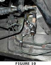 Spidertrax Disc Brake Kit utilizes the split front-to-rear system similar to the ?88.5-?95 models. By segregating the front and rear brakes, you are able to bias the rear brakes using a proportioning valve.
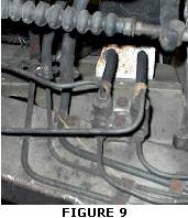
3) You will need to follow the lines from the master cylinder to the first manifold on the front passenger frame rail. This manifold is shown in Figure 9. This is off an ?87 Samurai.
4) Looking first at Figure 9 for reference, remove the top right brake line and the bottom left brake line. Figure 10 shows these lines removed.
5) Now reverse the location of the two lines and re-install. There should be no need to cut and flare these lines. Carefully bend these lines so they can be reversed. Once in 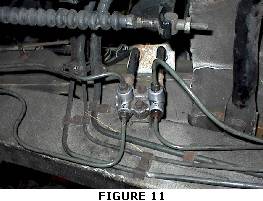 place, your manifold should resemble Figure 11. This is now a “split front-to-rear” brake circuit. Be sure that the repositioned brake lines are out of the way of the clutch lever.
6) Now you will need to install the proportioning valve. You will need to disconnect the brake line from the master cylinder that feeds the rear brakes. This line is the one furthest from the firewall.
7) Cut the flare off the end of this line and remove the metric fitting (cut off as little as possible to make re-installation easier). Replace the metric fitting with a standard 3/16 flare fitting and flare the line. 8) Figure 7 shows the brake line needed to install the proportioning valve. This brake line will have a metric fitting on one end for the master cylinder and a standard fitting on the other for the proportioning valve.
 9) Use the metric end to attach the new brake line to the master cylinder. Loop the line underneath the master cylinder and around to the proportioning valve. The proportioning valve will sit on top and in front of the master cylinder. Connect the standard end of the new line to the IN of the proportioning valve. This is different to the way the ?88.5-?95 is run because your new brake line will be attached to the port on the master cylinder furthest from the firewall. You can refer to Figure 8 for reference on the location of the proportioning valve; however, keep in mind that your new brake line will be connected to the master cylinder port furthest from the firewall.
10) Connect the existing brake line with the new standard fitting (from step 7) to the OUT of the proportioning valve. The line will have to be bent slightly to reach the proportioning valve.
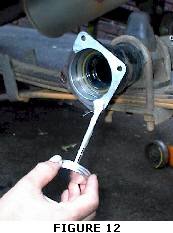
PART 3: INSTALLATION OF DISC BRAKES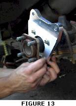 1) First we will apply a coat of anti-seize to the ends of the axle housing flange (Figure 12). Even though the caliper mounts are anodized, mating steel to aluminum can advance corrosion. Adding anti-seize is just an extra precaution. 2) With the rear axles free from the drum backing plates, slide the axles into the housing. Use a rubber mallet to assure the axles are seated properly in the housing.
3) Locate the 8 5/16″?18 grade eight bolts, the matching 8 nylocks, and the 16 grade eight washers included in this kit. Use this hardware to fasten the aluminum caliper mounts to the end of the housing (Figure 13). The Spidertrax logo engraved on the caliper mount should face the center of the axle housing. The 5/16″-18 bolts should be inserted from the outside of the axle housing. Use two washers per bolt (one on the head and one on the nut side). Recommended torque is 20-25 lb-ft.
4) Next locate the 10 OEM Suzuki wheel studs provided in the kit along with the two steel adapter plates. You will need to paint the adapter plates to prevent rust. Press the 10 wheel studs into the adapter plates. There is no front or back to the adapter plate. 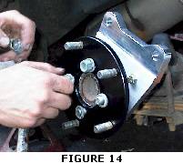
5) Place the adapter plates on the end of the axles shafts (Figure 14). The 4 original nuts and lock washers used to mount the drums will be reused to mount the new adapter plates.
6) Put the Suzuki rotor onto the adapter plate.
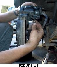 7) The caliper will now be positioned on the caliper mounts. Be sure to use new brake pads with the installation of the caliper. The caliper piston should be retracted in order to fit over the rotor. Slide the caliper over the rotor and line up the mounting holes with that of the caliper mount (Figure 15). Locate the 4 M12-1.25x30mm bolts along with the 8 flat and lock washers. Slide the lock washer onto the bolt followed by the flat washers. Insert the bolts through the caliper mount and tighten to 70-75 lb-ft.
8) Attach the brake hose to the steel brake line on the axle housing.
9) Remount the rear wheels and lower the vehicle
10) Finally check over all installed brake lines and fittings. You may have leaked gear oil during the removal of the axle shafts. Be sure that you have the proper amount of gear oil in the axle housing.
PART 4: BLEEDING THE BRAKES 1) It is best to have a partner when bleeding the brake system. One should sit in the vehicle and actuate the brake pedal (Driver), and the other will control the bleed screw (Bleeder). The Bleeder, who is under the vehicle, will give the order when to press the brake pedal. Good communication is key.
2) The Driver can fill the master cylinder with brake fluid. Keep an eye on the fluid level during this procedure to make sure it does not go below the minimum.
3) The Bleeder can crack all 4 bleeder screws on the calipers to allow the system to gravity bleed. Once a caliper drips fluid close its bleeder screw. 4) Starting with the rear driver side caliper, the Bleeder will give the command to the Driver to pump the brake pedal. After several pumps, the Bleeder will give the command to hold the pedal down firmly. At this point the Bleeder will crack the bleeder screw to release pressure in the line. The Bleeder first tightens the bleeder screw and then instructs the driver to release the brake pedal. The Bleeder will notice that a mixture of fluid and air will come out of the bleeder screw. When air is present in the fluid being released it tends to spray rather than stream. This process should be repeated for the rear driver side caliper until NO air is present. 5) Repeat step 4 on the remaining calipers in the following order: rear passenger, front passenger, front driver. Remember that the Driver needs to keep an eye on the fluid level in the reservoir. 6) At the conclusion of the brake bleeding procedure the Driver should have a firm brake pedal, meaning all the air has been removed from the system. With the new rear disc brakes, the brake pedal will travel slightly further before resistance is felt.PART 5: CALIBRATION OF THE PROPORTIONING VALVE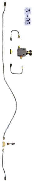 1) Properly calibrating your proportioning valve is critical for your new brake system. Without the proportioning valve, the brakes will distribute their power 50% in front and 50% in rear. This is usually not the case in a brake system since it requires more braking power in the front then in the rear. Generally when you use the 50% front and 50% rear braking power the rear brakes may lock up prematurely and the vehicle will slide sideways uncontrollably. The proportioning valve will allow you to reduce the rear braking power and thus increase the front braking power, say 60% front and 40% rear for example. We cannot tell you where to set the dial on the proportioning valve since the degree of proportioning depends on the size of tires and the type of suspension that is on your vehicle. What we will do in this section is explain the calibration procedures that are required to properly set the proportioning valve to your vehicle. We will be using Stainless Steel Brakes (SSB) proportioning valve available through most automotive retailers. 2) First, rotate the proportioning dial counterclockwise completely. This will “decrease” the braking power to the rear to the full capacity of the proportioning valve. Thus, with the SSB proportioning valve, the brakes will be proportioned 70% in front and 30% in rear. Find yourself an open lot to perform the braking test. Make sure that you have a pavement surface that is dry and without a lot of gravel and loose rocks. Drive the vehicle slowly and use the brakes to make sure they are actuating. It?s a good idea to find two other people to help calibrate the brakes. Have one person driving the vehicle with the other two watching the vehicle from the outside. Also, make sure you are wearing your seatbelt and that you are clear of other cars and people. 3) Next, drive the vehicle approximately 20 mph and attempt to lock the brakes. One person will be watching the driver side and one person will be watching the passenger side. When the driver attempts to lock the brakes, each person will record what happens to the front and rear tire. They may see three different situations: the front and rear tires lock simultaneously and equally, the front tire locks completely with the rear tire slightly chirping (on the verge of locking), or the front not locking at all and the rear locking completely. They should not see the driver side rear locking without the passenger side rear locking simultaneously. If this occurs, it may be due to a bad caliper or improper brake bleeding. If the front does not lock and the rear locks completely the vehicle will slide sideways so be careful. This should not happen if the proportioning dial is initially set as described in step 2 above. 4) In the “ideal situation”, the front brakes will lock completely with the rear just on the verge of locking or locking secondary to the front. The vehicle should brake in a straight line and should not slide or pull. You will need to repeat the test, turning the valve in 1/4 turn clockwise increments, until you get the “ideal situation”.
 5) In our testing, the ?94 stock Samurai was set 1/4 turn clockwise from the setting in step 2. However, some guys have found that with certain types of suspensions and tires, the proportioning valve can almost be entirely opened (all the way clockwise). Again, it depends on the vehicle. 6) Once you have achieved the “ideal situation” described in step 4, continue to drive the vehicle in the open lot to get familiar with the new braking power. Keep in mind that the feel of the brake pedal will be a little different as well. If you have any hesitation about the brakes working properly, you should contact us. Contacting Spidertrax via email is preferred but you can also contact them by phone. They have also supplied a FAQ?s section on their web page concerning the Disc Brake Kit.
DISCLAIMER WARNING: FOR OFFROAD USE ONLY INSTALLATION OF ANY COMPONENT OR KIT SHOULD ONLY BE INSTALLED BY PERSONS EXPERIENCED IN THE INSTALLATION AND PROPER OPERATION OF VEHICLE BRAKE SYSTEMS. BEFORE OPERATING THE VEHICLE, TEST THE BRAKES UNDER CONTROLLED CONDITIONS. MAKE SEVERAL STOPS IN A SAFE AREA AT LOW SPEEDS. THIS PRODUCT SHOULD ONLY BE USED FOR LOW SPEED OFFROAD APPLICATION. ATTEMPTING TO USE THIS PRODUCT ON HIGHWAY CAN BE HAZARDOUS.
08/11/10 15:09