 with Larry Harris
Spidertrax Disc Brake Installation
The Samurai has never been known as a speedster. Our little engine propels us down the trail at adequate speeds for most of our needs. The stock brake system was designed around this speed and our little stock tires. In the last few years the Samurai has come into to its own as a off road trail machine. It has taken a lot of work and time to get there. Many of us have swapped in lift kits, larger motors, lower gears. All this has been to achieve the goal of larger tires for improved ground clearance. These modifications come at a cost! Our once adequate braking is no longer first-rate as it once was. The Samurai braking system has been over looked by the aftermarket for years… Until now! Very recently released from Spidertrax is a complete system for adding Disc Brakes to the rear of our trucks. This kit come in a variety of stages for the do it yourself hobbyist.
Depending how much of the work and engineering you want to do on your own there are options to choose from. You can get just the Disc Kit or order the other fine kits from Spidertrax. These are the E -brake kit and the Brake Line Kit. When you install the disc kit you must make some provision for a E brake and line modifications. Spidertrax has foreseen these needs and offers engineered kits. Don’t have a flaring tool, or do not want to fuss with cutting and fitting your old lines, be sure to have the vendor include the Brake Line kit. There are other options for the E brake but you really need to ask, is it worth all the extra work?
The way I look at it is, let the manufacturer do the engineering. I opted for the complete kit selection. I am in this article going to show how double flares are done for those of you who want to make this a DIY project.
While working up this article I was going to take more pictures and do a quickie install write up. Going back to “why redo the engineering” I have adapted the excellent instructions that ship with the kit. What follows are the instructions you will receive when you buy this kit. They are reprinted with permission. Make sure to check out our review on this product by following this link.
Kit Includes You Supply May Need 2: Aluminum Caliper Mounts 2: Steel Adapter Plates 10: OEM Wheel Studs 8: 5/16-18 Grade 8 Bolts 8: 5/16-18 Nylocks 16: 5/16 Grade 8 Flat Washers 4: M10x1.25-30 Grade 8.8 Bolts 4: M10 Lock Washers 4: M10 Flat Washers Samurai front calipers and hoses (87 & up)
Samurai front rotors (87? and up)
Highly Recommended:
Spidertrax an E-brake kit
Spidertrax brake line kit
Note: If you do not use these kits you will need custom brake lines and a proportioning valve. This will also mean you will need some type of E-brake!
Rear wheel bearings
Rear axle seals
Tools:
Slide Hammer
Wrench set
Socket set
Flaring tool
Brake line wrench set
Miscellaneous:
Rags
Brake Fluid
Catch pan
INTRODUCTION: Spidertrax Disc Brake Kit. To begin, lets run down all the items that are included with this kit and explain their function. First, you should notice the two high quality aluminum caliper mounts. They are clear coat anodized to protect their surface from corrosion. The caliper mounts actually serve two purposes. They mount the calipers in place. In addition, they serve as the new rear bearing retainers. Next, with the elimination of the rear drums you will be left without a mounting surface for your rotors and wheels. That?s where the pair of adapter plates come in. These are designed to bolt onto the flanged end of the axle shafts. The five outer holes on the adapter plate will be used to accept OEM Suzuki wheel studs, which are included with this kit. You will also find all the necessary hardware that will be required to install the disc brakes.
You must supply your own Suzuki Samurai front calipers and hoses (?87 and up) and Suzuki Samurai front rotors (87? and up). Using this kit by itself will leave you with no e-brake at the rear axle. Spidertrax offers an e-brake system that mounts to the output of the transfer case. It uses a 7″ rotor and a mechanical spot caliper actuated by the stock e-brake handle. In addition, the Disc Brake Kit will require the use of custom brake lines and a proportioning valve. Spidertrax offers a supplementary kit , the Brake Line Kit, which includes these items. Although we explain the brake lines and proportioning valve needed (later in these instructions), purchasing the Brake Line Kit will save much time and effort.
To learn more about brake systems, we recommend reading Brake Systems by Mavrigian and Carley.
PART 1: DISASSEMBLY OF DRUM BRAKES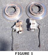 1) Gather the front calipers, hoses, and rotors that were taken off the donor Suzuki Samurai (Figure 1). Inspect the pistons of the caliper to make sure they are in working order. To do this, grab a large c-clamp. Put the ridged end of the clamp on the inner brake pad and the screw end of the clamp on the brake hose mounting bolt. Tightening the c-clamp should collapse the piston. If the piston doesn?t collapse, it may be seized in place due to corrosion and should not be used. Inspect the hoses for any cracks and dry rotting. Replace the hoses if they show any signs of wear. We recommend that the rotors be resurfaced at a local auto shop.
2) Now prepare the rear of the vehicle for disassembly. Chock the front wheels and loosen the rear lug nuts. Jack up the rear axle and support it with jack stands. Remove the wheels from the vehicle.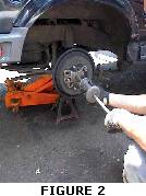 3) Make sure the e-brake is disengaged (e-brake lever should be in the down position). You will need to disconnect the e-brake cable from the vehicle. To start, remove both clevis pins located by the rear drum brakes. Follow the e-brake cable to the e-brake handle, removing all the supports that are present. Finally, remove the clevis pin at the e-brake handle. Keep in mind that the Spidertrax E-brake Kit utilizes the OEM e-brake cable so you may want to hold onto this. 4) Remove the four inner mounting nuts found on the drum. Using a slide hammer for assistance, remove the drum from the rear axle (Figure 2)
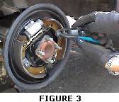 5) Now you will need to remove the brake shoes and springs from the backing plates (Figure 3). To remove the spring clips, push down on the open end with a flat head screw driver and rotate the holding pin 90 degrees with a pair of pliers. Once the clips are removed, pull the brake shoes out and towards each other. This releases the tension on the top and bottom springs. Remove the mechanical actuating lever from the packing plate.
6) Unscrew the brake line attached to the back of the backing plate. Remember that brake fluid will leak out of this line once it is removed. Therefore, you should place a container under the line. 7) Remove the four mounting bolts that hold the backing plate to the housing. Use the slide hammer to separate the axle shaft from the housing (Figure 4). The backing plate acts as a bearing retainer for the axle shaft, so make sure you remove the backing plate before attempting to remove the axle shaft.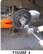 8) Its time to remove the backing plate from the axle shaft. The backing plate doesn?t just slide off since it is sandwiched between the rear bearing and the axle flange. There are two ways to approach the removal, either one works fine. The first option is to have a machine shop press off the rear bearing thus removing the backing plate. Keep in mind a new retainer ring will have to be used when the bearing is replaced. The second option is to cut the backing plate off of the axle shaft. Use a bench vise to secure the backing plate and carefully cut it off with a Sawzall. 9) The brake line setup will be different after you install the disc brakes. You must remove all steel brake lines that are present on the rear axle housing. 10) Finally take time to clean the axle housing before running the brake lines and installing the Disc Brake Kit.PART 2: OVERVIEW OF NEW BRAKE LINE SETUP
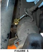 1) Notice in the title we are calling this section an “overview” of the brake line setup. We recommend using Spidertrax?s Brake Line Kit, but if you choose to run your own setup this section will give you the guidelines of what you need to do. 2) The pictures in the Brake Line Setup section show the brake line installation on a ?94 Samurai. Note that ?86-?88 Samurai?s use a different type of brake line setup then the ?88.5-?95. Also note all Samurai fittings are metric.?88.5-?95 Brake Line Setup 3) First, run a short brake line off the rear brake tab (Figure 5). This tab secures the brake hose coming down from the frame to the rear axle. Next , use a tee connection to split the line to both calipers. 4) You will have to run brake lines from the tee connection to both ends of the housing. Notice the end of the lines (where the brake caliper hose attaches) should bend back slightly (Figure 6). This is so the brake line does not hit the u-bolts. Be sure that if you are running an SPOA the brake line should also come down slightly to clear the leaf spring. Finally the end of the brake line should not pass the inner u-bolt. We used the existing brake line fasteners (located on the housing) to support the new brake lines.?86-?88 Brake Line Setup
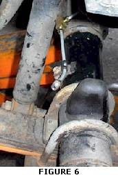 3) The installation for the ?87 will differ slightly then the ?94 shown above. First there are two hoses coming down to the rear axle. Route a single brake line to either side of the housing. The original brake line can be reused by trimming and flaring them to the correct length. 4) Although Figure 6 shows the setup on the ?94 vehicle, you can still notice the end of the lines (where the brake caliper hose attaches) should bend back slightly. This is so the brake line does not hit the u-bolts. Be sure that if you are running an SPOA the brake line should also come down slightly to clear the leaf spring. Finally the end of the brake line should not pass the inner u-bolt. We used the existing brake line fasteners (located on the housing) to support the new brake lines.
DISCLAIMER WARNING: FOR OFFROAD USE ONLY INSTALLATION OF ANY COMPONENT OR KIT SHOULD ONLY BE INSTALLED BY PERSONS EXPERIENCED IN THE INSTALLATION AND PROPER OPERATION OF VEHICLE BRAKE SYSTEMS. BEFORE OPERATING THE VEHICLE, TEST THE BRAKES UNDER CONTROLLED CONDITIONS. MAKE SEVERAL STOPS IN A SAFE AREA AT LOW SPEEDS. THIS PRODUCT SHOULD ONLY BE USED FOR LOW SPEED OFFROAD APPLICATION. ATTEMPTING TO USE THIS PRODUCT ON HIGHWAY CAN BE HAZARDOUS.
08/11/10 15:12